January 2015 – May 2015
Academic Group Project
I joined the team as Junior Engineer – Vehicle Dynamics and over the years have worked as Chief Technical Engineer, Captain and Driver.
Team Captain
As an administrator, my job was to take decisions that will first create better team and then create a better performing car which will help win trophies.
During my tenure as captain, I made following team contribution to:
- Change in team structure and hierarchy.
- Budget management and reducing recurring costs.
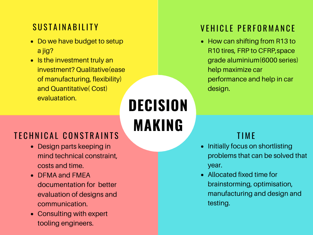
Following decisions were taken by subsystem heads and me.
Develop our own chassis manufacturing jig. (saves long term cost)
Setup in-house aerodynamic elements manufacturing facility. (saves long term cost)
Switch from R13 to R10 sized tires. (Weight reduction and and reduction in allied costs)
Switch from Yamaha 600cc engine to KTM 390 cc engine keeping in mind budget, recurring cost and technical constraints
Purchase tire data and establish a team for data analysis.
Chief Technical Engineer
Design Goals
- Low mass, Yaw inertia, CG height
- Minimize Compliance
- Reliability
- Making car Responsive
- Skidpad Time less than 5.3 secs.
- Target events Autocross and Endurance
- Tune for balance and grip
- Contact, Comfort, Control
- Tire Selection
Vehicle dynamics
Tire Selection
Selection of Rim size based on available budget, weight constraints, technical constraints.
Selection of suitable tire compound R25B or LC0 based on tire data.
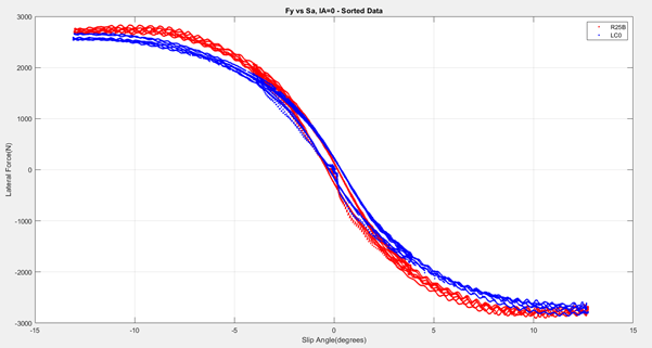
Tire Modelling
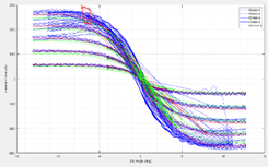
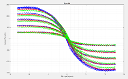
Data sorting in MATLAB to find variation of Forces and moments generated by tire in contact with road.
Finding Coefficients of Magic Formula (Pajecka Tire Model)
Dimensions
Selection of Trackwidth and Wheel Based to minimize Yaw Inertia and Optimize lateral and longitudinal weight transfer.
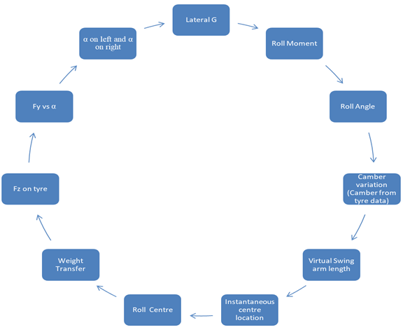
Suspension geometry
Kinematic geometry. Iterations to keep camber variation within limit to maximize tire grip while cornering.
Spring stiffness iterated to balance correct Ride Frequency, Static Compression, Rolling Stiffness.
Selection of Kingpin and Caster angle according to steering inputs such as steering effort and driver feedback.
Design of Anti-Roll Bar to provide required Roll stiffness.
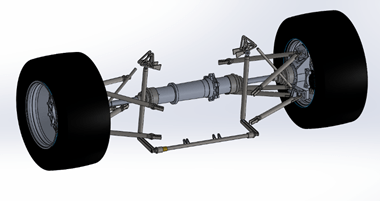
Wheel Assembly
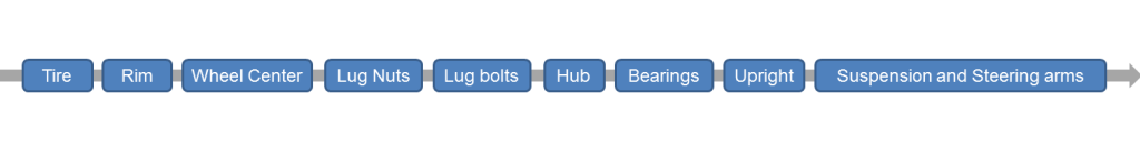
The above diagram helps to visualize the transmission of force from ground to vehicle chassis as well as tolerance stack up and part criticality.
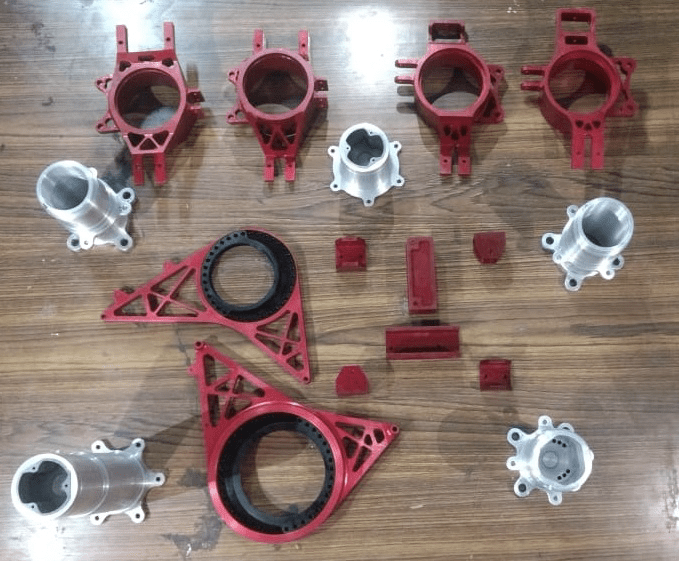
- Parts designed in Catia V5 and Solidworks
- Designing of wheel assembly requires inputs from Steering, Brakes and Suspension subsystems as well as manufacturing vendor.
- Parts were designed keeping in mind endurance limit of Aluminium.
- Critical Considerations: Bearing Selection, Manufacturing Cost, Raw Material cost, Material Procurement Time and Manufacturing Time.
- Chamfer for reducing stress concentration.
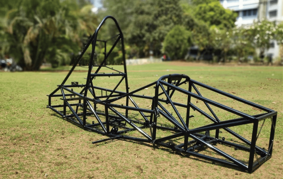
Manufacturing Jig
Problem
- Yearly budget constraint.
- Chassis extremely important.
- Distortion due to welding.
- Time
- Building from base to top.
- No proper referencing for vertical tubes.
Solution
1.Wood
- Inaccurate
- High assembly setup time
- Modular jig
- Difficult to modify
- High manufacturing time
2. Milled steel blocks
- High fixed cost
- High variable ost
- Less inaccuracies only in base frame structure
- Less Distortion
- Difficult to modify
- Vertical Alignment difficult
3. Aluminium Extrusion
- High fixed cost
- Low variable cost
- Easy to assemble
- Low setup time
- Easy to setup
- Easy to modify
- Reduction in manufacturing time
- Reduction in distortion
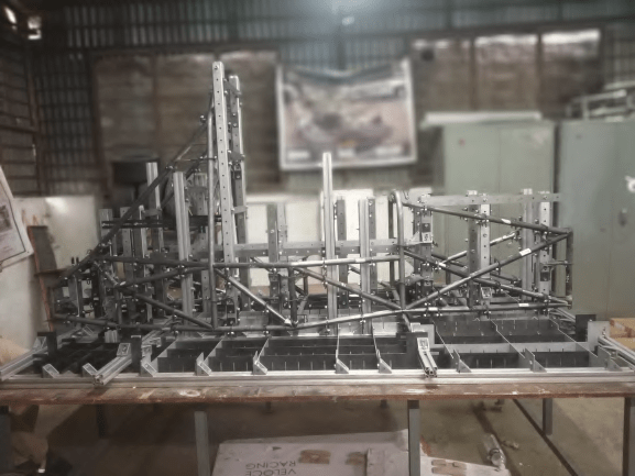
Jig
We decided to go with jigs made from Aluminium extrusions and Laser cut MS plates to place the notched AISI 1018 steel pipes for welding.
Inhouse Aerodynamics Element Facility
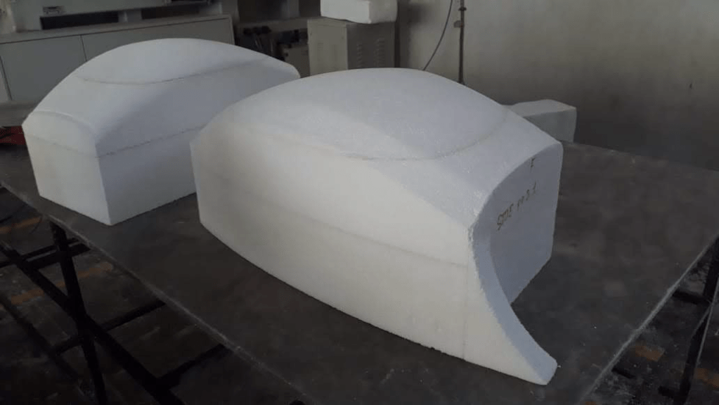
Material
Mold Material: Styrofoam.
Styrofoam stuck together using glue or purchased as a whole block.
Part Material: FRP/CFRP.
Available in rolls or sheets.
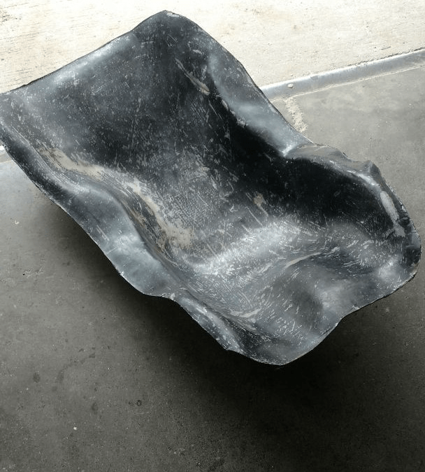
Manufacturing
Milling or Hot wire cutting to give shape to the molds from raw material styrofoam block.
Resin used to glue different layers of CFRP sheets.
Air drying process used based on available resources and budget.
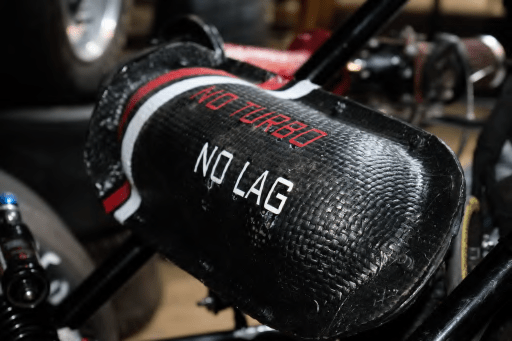
Advantages
Moving from FRP to CFRP led to weight reduction approximately 61%.
Developing aerodynamics elements in house saved cost by 40% – 50%.